The Class-A Amplifier Site
This page was last updated on 19 July 2004
Construction of a 20W class-A amplifier
1. General design
Jean Hiraga
(l’Audiophile No. 10)
A well known American acoustics expert remarked a few times, completely pessimistically: "One can make all progress which one wishes in the field of electroacoustics, it will nevertheless remain that all these systems always return to an impossibility: to want to make the music pass through an electric wire... (wire sound)".
One must indeed realize that an old gramophone with a directly engraved cylinder, in spite of important mechanical defects, contains the qualities that electric amplification has lost, because it does not display an unnatural and undue distortion. It appears that these distortions, purely mechanical, of a similar nature to the sound, that one can call "natural" seem much more bearable to the ear.
The amplifier is a very important link in the high fidelity chain and it must be of "low distortion" and "broad bandwidth", something that many audiophiles know. The essence is not that it is class A or B, with simple or complex circuitry, or containing very special or modern components, but that it is quite simply faithful. This automatically includes all the concepts in respect of character, dynamics, tonal balance and exactness in the reproduction of the musical image. A piano tuner, who is not inevitably able to appreciate high fidelity equipment, could make comments previously (thought) completely stupid, as for example to say that an amplifier modifies the character (timbre) of a piano and even the volume of the sound. This same remark could be made for a turntable or a loudspeaker. But if we look at the contents of a piano note, which can be made up of more than thirty sinusoids, fundamental plus harmonics, without counting the sympathetic reverberation, the resonance of the bass, etc... each one of different and precise level and phase. By adjusting the highest amplitude sinusoid (it is not inevitably the fundamental one, but generally the second harmonic) to 100 dB for example, one notes that the other harmonics are located at a lower level, that is to say between 0.1 and 10 dB.
For the reproduction of the same note in an apartment, this level of 100 dB is too high, which means to say that listening at 10 or 15 dB less will still reduce in level all the other harmonics.
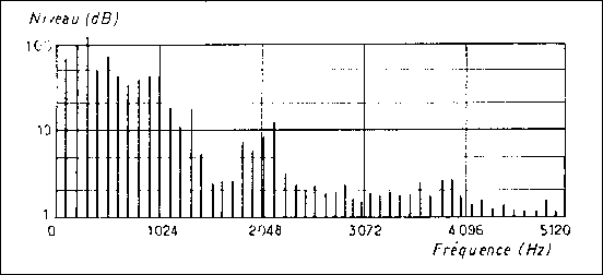
Fig. 1 : Harmonic spectrum of a trumpet (fortissimo).
Examine figure 1, it illustrates the spectrum of a trumpet. Let us pass now to the contents of the distortion of some amplifiers of which some are very known (fig. 2). It is noted that, in spite of a low total rate of distortion, the various circuits intended to reduce the rate of distortion can practically never reduce to an equal level each harmonic: some are prevalent, others completely absorbed by one of the negative feedback loops. Also notice that for a different level, this spectrum sometimes changes completely. And it is not only one frequency. If an amplifier presents a very irregular spectrum of distortion and if it is subjected to a relatively simple musical signal, such as the one indicated in the preceding figure of the spectrum of a musical instrument, it gives obligatorily deformations, sometimes being able to reach more than 8 dB for a given harmonic. These differences, minor or important, of level or phase for each harmonic, thus generate a different envelope which deforms the nature of the sound reproduced. This also plays with the dynamics, because the envelope of the sound is made up from combination of the levels of these various harmonics.
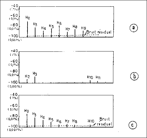
Fig. 2: Harmonic spectrum of distortion of three amplifiers A, B (Japanese
equipment, very top-of-the-range) and C (bottom-of-the-range equipment
but excellent, out of production).
One should not however allot these defects to a badly thought-out circuit but rather to the rates and the "non-camouflaged" spectrum of distortion of the active elements.
If one takes a very good triode, such as the English PX 4 or the PP3/250, the rate of distortion is only 2 %, with the second harmonic prevalent. If one passes to the KT66, the KT88 or the EL34 (which is however a good pentode) this rate becomes 6-8 %. As for a bipolar transistor, it is definitely lower on this point. Trying again, this time the excellent KT66 in linear ultra push-pull assembly, taken to 43 %, this rate becomes 2 %. But these 2 % do not have the same harmonic contents at all as a true triode PX4: they are made generally of a reduced second harmonic (cancellation by the push-pull circuit), of increased third harmonic, with fourth harmonic practically absent and an irregular remainder. It is understood that other negative feedbacks can arrange the things, but they are then completely special circuits, "acrobatic" and difficult to control. Another annoying consequence is that this interesting reduction of the distortion is accompanied by a loss of stability of the unit (risks of rotation of phase, rate of negative feedback raised, etc). This is why, for the same technical training in the fields of the transistor and the tube, it is more difficult to produce a good transistor amplifier, for the simple reason that this active component taken by itself has too many defects, the "camouflage" of which is very difficult.
And this is not the only problem of the transistor amplifier: let us consider the advantage and the disadvantage of the direct connection with the loudspeaker, its effects on the negative feedback loop (the effect of the back-electromotive force of the loudspeaker re-injecting the signal into the amplifier), the effects which were well known to Matti Otala and John Curl. Also let us note the undeniable difference existing between a tube and a transistor, for the speed of the electron which, in the vacuum, is at least 7 times faster than in the structure of the semiconductor.
There is still another point directly dependent on the damping factor: it concerns the power characteristic in relation to the impedance of the load. In tube equipment, this only varies a very little and thus adapts well to the loudspeaker. In a tube OTL amplifier (Output Transformer-Less), the ratios of: internal impedance of the tube - maximum power - impedance of load still favour the loudspeaker which will receive the maximum energy in the neighbourhood of its resonant frequency.
On the other hand, in a transistor amplifier, with rare exceptions, the output power increases when impedance of load decreases, sometimes in a significant way for a difference of a few ohms. Considering the transitory instability of the impedance characteristic of the loudspeaker under operation, the protective circuits, the transistors being able to chop or modify the instantaneous level, it becomes really very difficult to design piece of equipment of great musical fidelity, and the true successes could be the fruits only of extraordinary chances or a piece of equipment studied at length, improved and ... listened to.
Moving on to the circuits, a detailed study can easily extend over many pages. However, most interesting in a circuit is not the circuit itself, but its philosophy, the required goal and the means by which you try to reach it. A simple and well studied circuit is increasingly more difficult to conceive than a complicated circuit, and many good examples exist in circuits with tubes and with transistors: the circuits of Dynaco, Quad, Williamson ... illustrate them.
20 Watt Class-A Amplifiers
Readers always wondered why the Kanéda amplifier has not yet been described in Audiophile. Several reasons exist: the delicate choice of certain transistors, the exact matching of these, in particular for temperature, the delicate assembly of the power supply and especially the intense heat released by the heatsinks spending "unnecessarily" 2/3 of the consumption in calories.
Just like an amplifier with large power tubes, the release of heat is intense. The "normal" 100 degC temperature of a heatsink always worries. If the different components are of good quality, the problems do not appear immediately but in the following year or years: transistors which "do not hold", change in values of the components, capacitors starting to leak or becoming virtually short-circuit, results in dc offset the effect which (because of direct connection) changes the rest position of the voice coil, etc. It is thus not simply a question of sound quality but a question of reliability.
For this reason it seemed preferable to us to start with a small class-A amplifier of 15-20 Watts of power, already largely sufficient for a listening in an apartment with speakers of good output.
But let us reassure the readers, this is by no means a deficiency. A very powerful amplifier always uses many output transistors in parallel which will quickly degrade the sound quality: (due to) the increase in the base capacitance, perfect matching being impossible, and most importantly, (it being) very difficult to stabilize the current in crossover region ...
Whether the amplifier is 20 Watts or 500 Watts, we always remain faced with an impossibility: that is to try to reproduce the real level of the signal. Table 1, which gives the lowest and highest levels of various instruments of an orchestra, indicates to us that a loudspeaker of 3 % output efficiency should be rated at 2200 Watts (the problem of the neighbours is not tackled) to reproduce the dynamics of an orchestra of 75 artists. We are thus far from the truth, in the maximum level as well as the minimum, by the great insufficiency of the signal-to-noise ratio. This same table shows the obvious loss of definition, if the scale of these levels is reduced to a level "in apartment", which is actually an effect of sound compression and limits in the signal-to-noise ratio of the recorded signal.
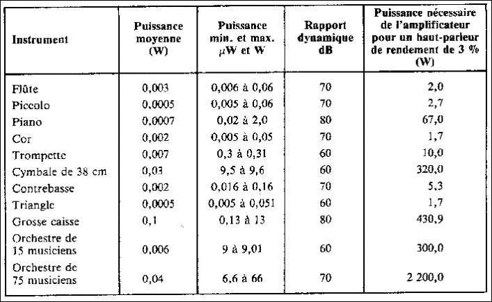
Table 1 : Acoustic level of various instruments and theoretical power of the amplifier required for a loudspeaker of 3 % output efficiency for the restitution of these levels. Notice that the acoustic level for an instrument can be as low as 0.005 microwatt, as the piano has the greatest dynamic ratio (80 dB) and that, for an orchestra of 120 musicians plus a choir of 200 people; the dynamics can exceed 120 dB.
Symmetrical circuit or not?
In circuits with tubes or transistors, the perfectly symmetrical circuit is always respected by many amateurs. For a circuit with tubes, entirely symmetrical and push-pull, connection by transformers is the simplest. Other circuits like the Paget and the Loyez are symmetrical. With transistors, it is a little delicate: even by using quasi complementary pairs, the impedance of the upper symmetrical part is seldom identical to that of the lower part. At low levels, this imbalance of the impedances results easily in a clear increase in the rate of distortion. It is what figure 3 represents. The phenomenon is called in the USA and Japan "hard distortion", compared with the "soft distortion" of a good tube amplifier.
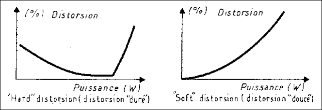
Fig. 3 : Two types of distortion. On top, "hard distortion" characterized by the effect of imbalance of the upper and lower branches. On right-hand side, "soft distortion". This is the type called a "natural" distortion such as that of a triode tube or a tube amplifier without negative feedback.
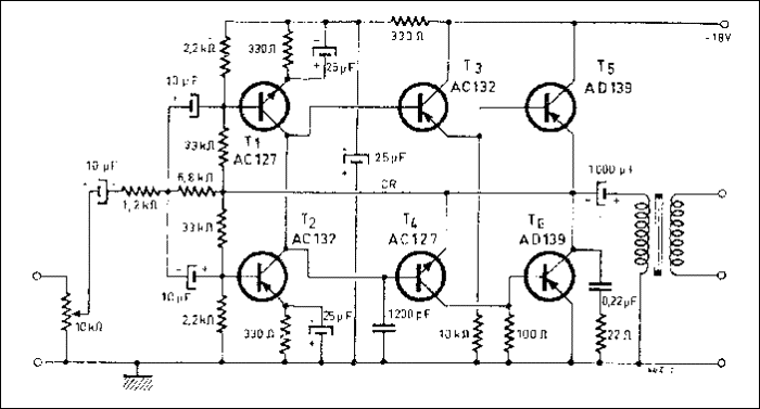
Fig. 4 : An old balanced amplifier circuit (1970, Revue du Son).
Figure 4 shows an example going back to 1970 of a symmetrical circuit for an intercom (Revue du Son No. 212, Dec 1970) the only reservation which one can make is to see that it is not entirely direct coupled from the input to the output.
There are other circuits, involving the more recent techniques, of which some are extremely complicated but clever, (which are) completely symmetrical, such as those amplifiers like A and E, GAS Ampzilla, etc. Of the very recent circuits, let us note in passing the Sansui "Diamond" circuit which is also a symmetrical circuit, with differential input using field effect transistors (fig. 5).
This circuit was not used here :
1) by refusing to insert diodes in series with the drains of the FET, the inclusion of which can have an awkward subjective effect.
2) by fear to lose some dynamics by inserting a current regulator in the sources of the differential pair.
In spite of the excellence of the "Diamond" circuit, a simpler circuit was desirable for amateur use.
Another input circuit, entirely symmetrical and using two differential pairs, figure 6, was also not used. It is certain that, except if these two pairs really are perfect pairs in all respects, the negative feedback loop applied to the bases of the branch opposite to the input can introduce a distortion (because the "opposite" is imperfect). It would not be at all practical to want to apply the negative feedback to the input.
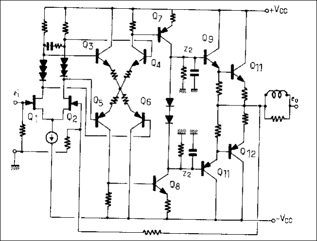
Fig. 5 Circuit of Sansui "Diamond", very powerful, low TIM and high slew-rate.
Circuit Philosophy
This circuit does not have the claim to be "the best" or the best developed. Simply, it contains only 8 transistors, including two power devices.
Developed for an output power of 20 Watts, in class-A (pure class-A, not assisted polarization) it must satisfy the following requirements
- Simplicity of the circuit : 8 transistors.
- Non-critical adjustments.
- Direct coupling of input and output.
- Output power not very dependent on the impedance of load or even increasing slightly with an increase in impedance.
- "Soft" distortion characteristic (rate of distortion going up steadily with the output power increase).
- Low rate of negative feedback (15 to 20dB maximum).
And, of course, excellent musical fidelity.
Input stage
The selected input stage is not a differential circuit: (this is) a practical question and that of economy, because a good differential pair PNP/NPN is either expensive or difficult to find, which comes back to the same thing. Indeed, even in Japan where quality components are easily found, it is rare that the specialized stores, sometimes even those only (dealing) in semiconductors, sell the first grade devices. The best transistors are almost always reserved initially to the large manufacturers, for whom the stability of performance in the mass production is of primary importance. In addition, a retailer concerned about the amount of his stock never dares to place an order, which can easily range between 1 000 and 10 000 parts, for first grade transistors. Thus amateurs having tried out many circuits were quickly disappointed by the results obtained, going so far as to doubt the sincerity of an article published in a technical review. It is always the case, even now, that it is necessary to get at least 100 transistors in a reputable store to be able after sorting, matching (attempted matching!), comparison of the pairs selected under hot or cold air blast (a hair drier or Freon gas can do the job perfectly), to draw a few good pairs from them. Because the smallest drift, amplified directly by the circuits, will cause, as indicated above, a displacement of the rest position of the voice coil, which is to say a non-linearity of displacement of the cone, a non-linearity of the flexibility of the moving element, a loss of linearity of the magnetic field, a reduction of the available power, and even an increase in distortion.
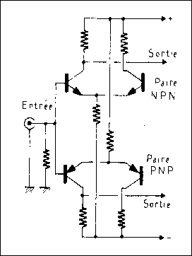
Fig. 6: Diagram of input stage using two differential pairs.
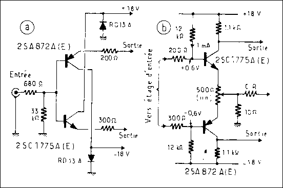
Fig. 7: The input circuit used, of a "double emitter follower" type and the second stage,
employing the same transistors.
This is why, while being directly coupled, the differential circuit was removed and replaced by the circuit of the figure 7a. This circuit, without gain, using complementary transistors is of a "Double Emitter Follower" type. The collectors connected directly to the supply confer an optimal stability to this stage.
The transistors used are of a low noise type, (designed) for audio use, the perfectly complementary Hitachi 2SC1775A and 2SA872A. These pairs, (epitaxial silicon) which have a Pd of 300mW, a Vcbo maximum of 120V, a ft of 200MHz, have been used in several recent amplifiers and preamplifiers because they are excellent from all points of view. Cased in Jedec TO92, it should be noted that their minimum hfe in different batches is not completely the same for the 2SC1775A and the 2SA872A, i.e. it is distributed between 400 and 2000 for the 2SC1775A and 250 and 800 for the 2SA872A.
Each part has, besides its number, a sorting reference, that is to say D and E for the 2SA872A and E, F, G for the 2SC1775A. It is thus necessary, not only to get first grade devices, but also batches of identical sorting, i.e. the reference E, that is to say an identical hfe for the complementary pair, distributed between 400 and 500. Also note that the same parts without suffix A are second grade, for which the maximum electrical characteristics are lower.
Second stage
The link to the second stage is made via two resistors of value 200ohms and 300ohms, the values are slightly different and are intended to balance the impedances of the lower and higher symmetrical parts. Two resistances of polarization of 12kohms adjust the current of the power transistors to 0.95 A. One can, if one wishes to vary this current or to pass from class A into class A2 or AB1, replace these values by a resistor of 10kohms and an adjustable resistor from 3 to 5kohms, fig 7b.
This second stage, composed of the same transistors but of opposite polarity for each symmetrical part compared to the input stage, is charged by resistors of 1.1kohms, the value selected according to the gain of the unit. The emitters are connected to the trimmer and the negative feedback circuit whose advantage it is to work at low impedance.
Output stage
The output stage is of a particular design, especially with regard to the choice of the transistors and the combination of the characteristics of the transistors, it is the subject of patent application.
At first sight, figure 8 of the output stage makes us think of a combination known as Darlington.
Actually, it acts as another circuit baptized "reversed Darlington" or "Darlingnot", because one must notice the opposite polarity and operation of collector-follower of the driver transistor. The emitter of this transistor receives, by negative feedback, the signal of the collector of the power transistor, whose characteristics are in effect modified. This effect is completely comparable with the "Ultra-linear" connection of a push-pull circuit using tubes. Its role is very important concerning the properties desired for such an amplifier, as indicated above. These transistors, NEC 2SA634 and 2SC1096 allow, coupled with the output transistors 2SA649 and 2SD218, an optimum combination. The only regret is that this complementary pair of power transistors is not manufactured any more. Giving the 50W class-A Kanéda amplifiers (connection in parallel) the best results that one can have, these pairs are now replaced by the 2SC188 and 2SA627 which are fortunately of very similar quality. These transistors are also used at output of the Kanéda 15 Watt amplifier, which is also an amplifier with a very high level of quality and whose only defect is the power supply, which is complex and difficult to regulate (see figure 9).
Here, the many extremely interesting "gadgets", however, are replaced quite simply by two Zener diodes (input circuit) limiting the current in the event of overload and 0.47ohms resistors limiting the current in the event of short-circuit of the output.
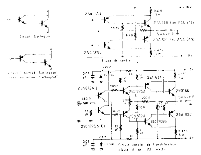
Fig. 8 : The output stage of a reversed Darlington type and the complete circuit of the 20 Watts class-A amplifier.
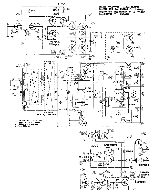
Fig. 9 : Diagram of the power supply circuit of the 2 x 15 W Kanéda Class-A amplifier
Power supply
This one is very simple (fig. 10). It uses only very large capacitors (2 x 189 000 uF) whose advantages are described by Mr. Marec. This value of 189 000 uF, although high, seemed however still insufficient for such an amplifier. For the RIAA stage of the Kanéda preamplifier, tests showed very clear subjective improvements for values reaching 450 000 uF (instead of 39 000 uF), in particular a better "focusing" of the sound images, a real sense of depth and especially much better dynamics. The large disadvantage of such supply is its size and the input current at the time of switch-on, requiring rectifiers of high amperage and a series resistance limiting the inrush current at switch-on, not to mention the cost price.
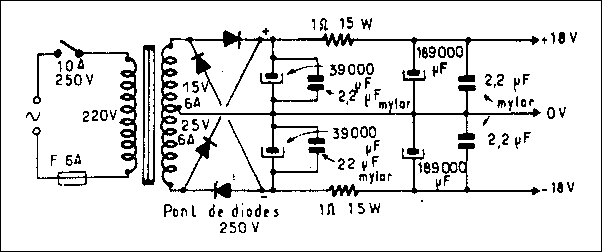
Fig. 10 : Diagram of the power supply
The Performance
Although very simple, this circuit whose total gain is (8 + 32 - 16)dB, that is to say approximately 24dB makes it possible to obtain, depending on supply, between 18 and 20 Watts (class-A).
With this power, the rate of distortion reaches practically 1%. It is due mainly to the supply which is limited here purposefully to + and - 18volts, to increase the lifespan of the power transistors.
On the other hand, the rate of distortion goes down steadily to less than 0.01% at 1Watt and even less at the lower levels just above the limits of the residual noise. Between 4 and 20ohms, the output power only varies a very little and even increases slightly above 8ohms. This effect would be even more pronounced without the effect of the negative feedback.
Let us add that the 500ohms trimmer (second stage) adjusts and cancels the DC voltage at the output and that the safety margin used makes it unnecessary to use thermistors to adjust the currents. Carefully adjusted, the first 4 transistors with the opposite characteristics, offer an effect of auto-compensation of distortion, making it possible if they are well paired, to remove the 500ohms trimmer and to replace this by two resistances.
With regard to the bandwidth, the choice of the transistors, the diagram retained with its circuits with low impedance, makes this amplifier linear to -1dB from 0 to 100 kHz.
Subjective qualities
Contrary to many inadequately designed transistor amplifiers, using badly selected transistors (from the technical point of view, as well as subjective) this amplifier when listened to "blindly" makes one think of a good tube amplifier rather than a transistorised amplifier. With a soft, dynamic, refined sound, one should note that, like some other class-A amplifiers, it gives the impression of being much more powerful.
In the following chapter the details of the mechanical construction will be given as well as the types of passive components used (fig. 11).
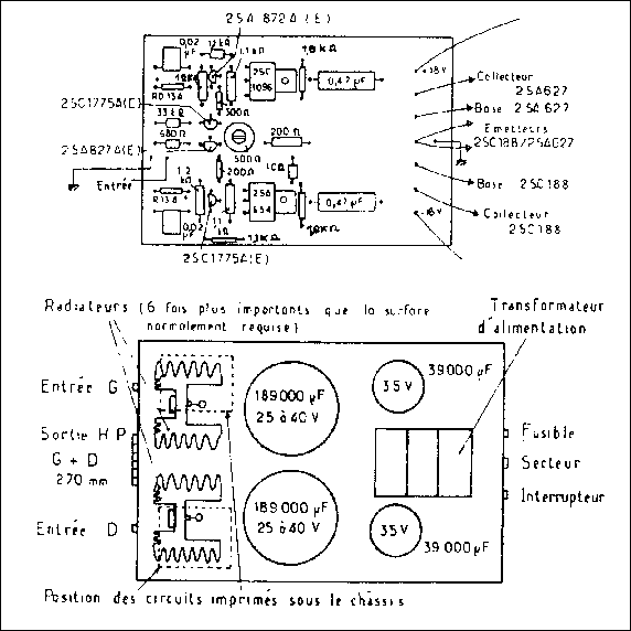
Fig. 11 : Disposition of the components on the circuit and chassis.
HISTORY: Page created 19/07/2004