The Class-A Amplifier Site
This page was last updated on 7 May 2001
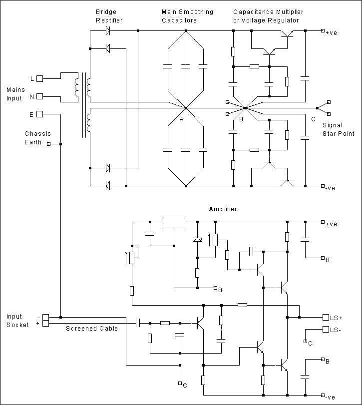
Earthing
Correct earthing is essential to minimise the possibility of noise being injected into signal lines and to reduce the likelihood hum being created by ground-loops. The diagram below gives my suggested earthing arrangements.
For safety, the mains/chassis earth must be connected to the amplifier. This connection must not be made at the transformer centre-tap or the reservoir ground (point "A"in the diagram) since the voltage at this point will be affected by the high capacitor charging pulses. Connection at this point will cause severe ground-loop hum when the amplifier input is connected to source equipment that has its own mains earth connection.
Connecting the mains earth to the star point (point "C" in the diagram) is better, but this can still cause audible hum due to the resistance of the connection between the input and the star point, since this connection will still carry any ground-loop currents. The best arrangement is to connect the mains earth to the chassis and then to the input socket, as shown in the diagram. This will minimise the possibility of hum due to ground-loops.
Supply rail decoupling capacitors and other non-signal carrying parts of the circuit should have a separate earth return path to the reservoir ground point so as to avoid injecting noise into the signal earth. Similarly, the earth returns from the components in capacitance multiplier or voltage regulator (if used) should have separate paths back to the reservoir ground.
Every effort should be made to keep the input earth and the feedback earth at the same potential since any difference between the two will appear at the output of the amplifier.
Ideally, points "A"and "B" in the diagram should be the same physical location (for example a large earth-bar). However, this is not always a practical arrangement if a capacitance multiplier or voltage regulator is used and so two, separated points have been shown. If a simple rectifier/capacitor power supply is used, the supply rail decoupling capacitors etc. should be returned to point "A".
The signal star point should be joined to the reservoir ground through a short, thick connection. Under no circumstances should the reservoir ground be used as the signal star point, due to the high capacitor charging pulses present in this part of the circuit.
Note also that the output from the rectifiers should be connected directly to the smoothing capacitors and then the dc output taken from the same point to the capacitance multiplier, voltage regulator or amplifier. Under no circumstances should the capacitors be "teed-off" as this will put sharp pulses on the supply rail and will cause an increase in hum.
Please also note that mains switching, ac fuses, dc fuses and output fuses have not been shown in the diagram. This is not to suggest that these essential safety requirements are not necessary. The diagram is solely intended to show the preferred earthing layout, not the full circuit.
Though I have shown the circuit of the 1996 version with a dual-rail power supply, the same principles apply for the 1969 version with a single supply rail.
For further guidance on earthing, and pcb layout in general, I recommend Doug Self's Audio Power Amplifier Design Handbook, (2nd edition). Chapter 13 gives plenty of useful information on these topics (and the rest of the book is worth reading as well). Additional information can also be found in the Earthing article at the ESP Audio Pages.
HISTORY: Page created 07/05/2001