The Class-A Amplifier Site
This page was last updated on 4 February 2002
A JLH Class-A for the Quad ESL57
Credits: Original design - John Linsley Hood
Circuit modifications - Geoff Moss
Layout, pcbs and construction - Nick Gibbs
This version of the JLH Class-A amplifier is the result of a series of emails and design discussions which culminated in the subsequent construction of two high current amplifiers specifically optimised to drive Quad ESL57 electrostatic speakers.
Some months ago, I received an email from Nick Gibbs regarding his 1969 JLH and a possible upgrade to a 1996 version with a higher quiescent current. Nick's 1969 JLH was about 16 years old and had been in almost daily use. It had a 27V supply rail and a quiescent current of 1.2A and Nick was using it to drive his Quad ESL57s, since neither his Quad 405 nor JLH MOSFET amps would do so without tripping the protection circuits. The little 10W JLH worked well with the ESL57s, albeit with some occasional clipping on louder passages, and Nick felt that a higher current version would best meet his needs.
The ESL57 is a difficult load to drive in that it is capacitive and its impedance drops to a low of around 2ohm at 15kHz. A high current delivery is therefore required but, to offset this, the maximum voltage that should be applied to the ESL57 is only 33Vp-p. It seemed that a JLH Class-A with a reduced supply rail voltage and a higher quiescent current would be ideal.
After we exchanged a number of (sometimes lengthy) emails, the final design evolved. It was a cross between the 1969 and 1996 versions (hopefully with the better parts of each J) operating off +/-20V supply rails and with a quiescent current of between 3.5A and 4A. The circuit is shown in Fig.1, but it should be noted that Nick used MJ802 output transistors in place of the 2N3055s since he already had these devices available.
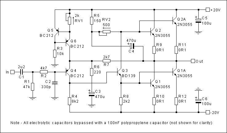
Fig. 1 - The Final Circuit.
As can be seen, the circuit is a mixture of the two original JLH versions, with modifications to enable an increase in quiescent current. Parallel pairs of output transistors have been used to keep the dissipation in each device at an acceptable level. The 0R1 emitter resistors are included to ensure equal cu+rrent sharing between each device. The quiescent current control is the standard 1969 bootstrap method whereby C4 maintains a constant voltage across RV2 and thus a constant dc current into the bases of the output transistors.
The input stage of the 1996 version has been utilised, but for dc offset control the 7815 has been replaced with a constant current source to avoid the instability problems that have been encountered when the 7815 is operated at a low current. Several capacitor values have been increased to modify the low frequency ‑3dB point and to reduce low frequency distortion. High quality components have been used throughout.
Addendum - 4 February 2002
Note, care must be taken to ensure that R5 and RV2 are adequately rated. The current through these components is slightly greater than the sum of the output transistor base currents. The output transistor base current is the output transistor quiescent collector current (Ic) divided by the current gain (Hfe) of the device. The current through R5 and RV2 is therefore approximately equal to 4 x Ic / Hfe and this should be calculated for the chosen output transistor quiescent current and output transistor type. It is recommended that output transistors with a gain of 100 or more at the working collector current are used in this design to reduce the power rating requirements for R5 and RV2.
Whilst it should not be difficult to obtain fixed resistors with the required power rating, the preset potentiometer could be more of a problem since the more common ones are only rated at 0.5W or 1W, though higher rated devices are available. It must be remembered that the power rating of a preset, when connected as a rheostat, is proportional to the length of track in use. The required power rating must therefore be calculated from the current flowing through the preset and the full preset resistance value.
With high gain (>100) output transistors and a quiescent current of 3A, a 1W device should be adequate for R5 and 2W for RV2, provided RV2 is no greater than 500ohm. If a larger value of RV2 is found to be necessary, it will be best to use a 2W fixed resistor in series with RV2 to avoid the need for a higher power rated preset. (Note, the original value shown in the Fig. 1 for RV2 was 2kohm. This value has been changed due to the power rating considerations).
If RV2 needs to be set to below about 300ohm due a particular combination of quiescent current and transistor gain, I suggest that R5 be reduced to between 50 and 100ohm to avoid the need for increasing the size of the bootstrap capacitor C4.
The power supply (one for each channel) is shown in Fig. 2. This is basically the standard LM338K circuit, included elsewhere on this site, with some capacitor variations/additions.
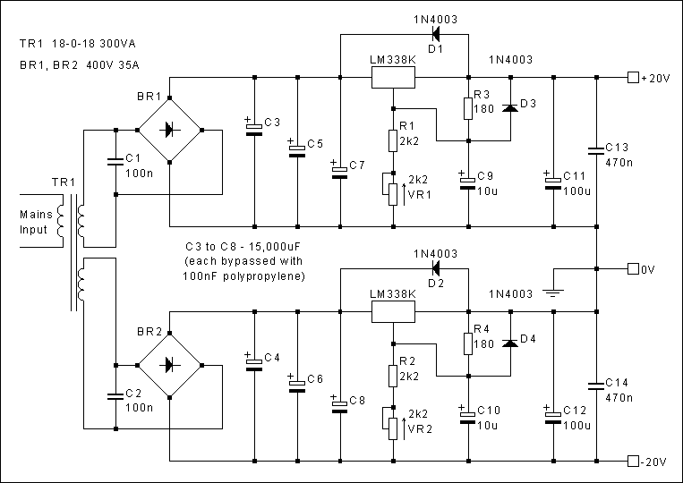
Fig. 2 - The Power Supply
Nick initially adjusted the quiescent current to 3.5A but found after listening tests that increasing this to 4A gave a noticeable improvement. Even at an Iq of 4A the amps run cool due to the substantial heatsinking (0.5degC/W for each output device and each LM338K). Variations in quiescent current and dc offset with temperature are minimal, with an Iq of 3.8A and a dc offset of less than 35mV at switch-on.
As for the sound quality, Nick's initial comments are summarised below:
I have just spent two hours listening ... I cannot believe the improvement over my old JLH. I have ended up with 20V rails and an Iq of 4A. You may well understand that I am feeling a little emotional at the moment so I will attempt to quantify the sound in a point form:-
Female vocal - incredible, makes the hairs on the back of my neck stand up.
Instruments and singers now appear as solid 3D objects, they have constant depth, if that makes sense?
No blurring of image or loss of depth on loud moments.
Acoustic guitar - real!
Bass - although the ESLs are 3dB down at 55Hz everything is so well defined, I would say at this point that my old JLH was brilliant here too.
I can hear more hiss from the source material, although I cannot as yet fault the top end reproduction, the ESLs are very revealing.
I think more than anything else it's the fact that the amps NEVER appear to get confused (?) (increasing the Iq from 3.5A to 4A prevented slight confusion/clipping (recovery) with heavy mid to upper band periods, at the levels I listen at). Constant image solidity, depth and remarkable detail at all times are what these amps are about, bloody brilliant!
I have broken into my Cambletown Whisky as celebration
And a few days later:
The amplifiers just get better the more you listen, real instruments and human voice are truly superb and very involving, plus of course the sensational 3D solid imaging. I wish you could hear them.
I am slowly working my way through my CD collection with the new amps, and it just gets better!
And Nick's most recent comments:
The combination of Marantz CD17 MkII + new amps + ESL57 is the first system that I have EVER heard that can do justice to the sound of a piano. I have been listening to a Deutsche Grammophon recording of Liszt's Hungarian Rhapsody, a little hissy, but for the first time, the attack (?, I don't know how to describe this), the first instances of a piano note and all that goes with it to convince you that you are listening to a piano, is there. I have friends who play the piano and so I often listen to the real thing. I consider this ability of the new amps very important. I thought the ESLs would give me this with pretty much any amp, but it has taken the new JLH amps to actually do it. Additionally, the insight into Bizet's Carmen, again on Deutsche Grammophon, is exceptional.
Increasing the size of the electrolytics from 220uF as in my original JLH to 470uF has very noticeably extended the bass response.
The original JLH is a magnificent amplifier, but with the modifications it has become outstanding."
Circuit Boards
Nick has kindly supplied me with a copy of his pcb layout for both the amplifier board and the regulator board in case they are of interest to other constructors. These are reproduced below at full size. It should be noted that the amplifier board is laid out for Caddock MP930 series power resistors, on heatsinks, for R5, R9, R10, R11 and R12 and also that Nick has used two resistors in series (100ohm and 50ohm) for R5 as these were more readily available (and cheaper). Component overlay diagrams have also been included after the pcb diagrams.
The actual board sizes are: Amplifier board 8.55 x 5.25 (217mm x 133mm)
Regulator board 3.3 x 2.9 (84mm x 74mm)
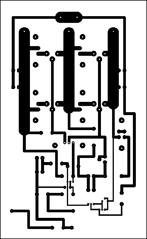
Fig. 3 Amplifier pcb (viewed from copper side)
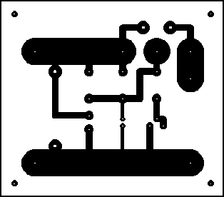
Fig. 4 Regulator pcb (viewed from copper side)
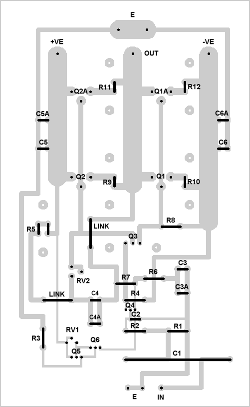
Fig. 5 Amplifier pcb overlay (viewed from component side)
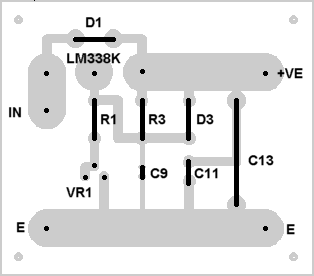
Fig. 6 Regulator pcb overlay (viewed from component side)
Finally, for those of you interested in seeing the results of Nick's labours:
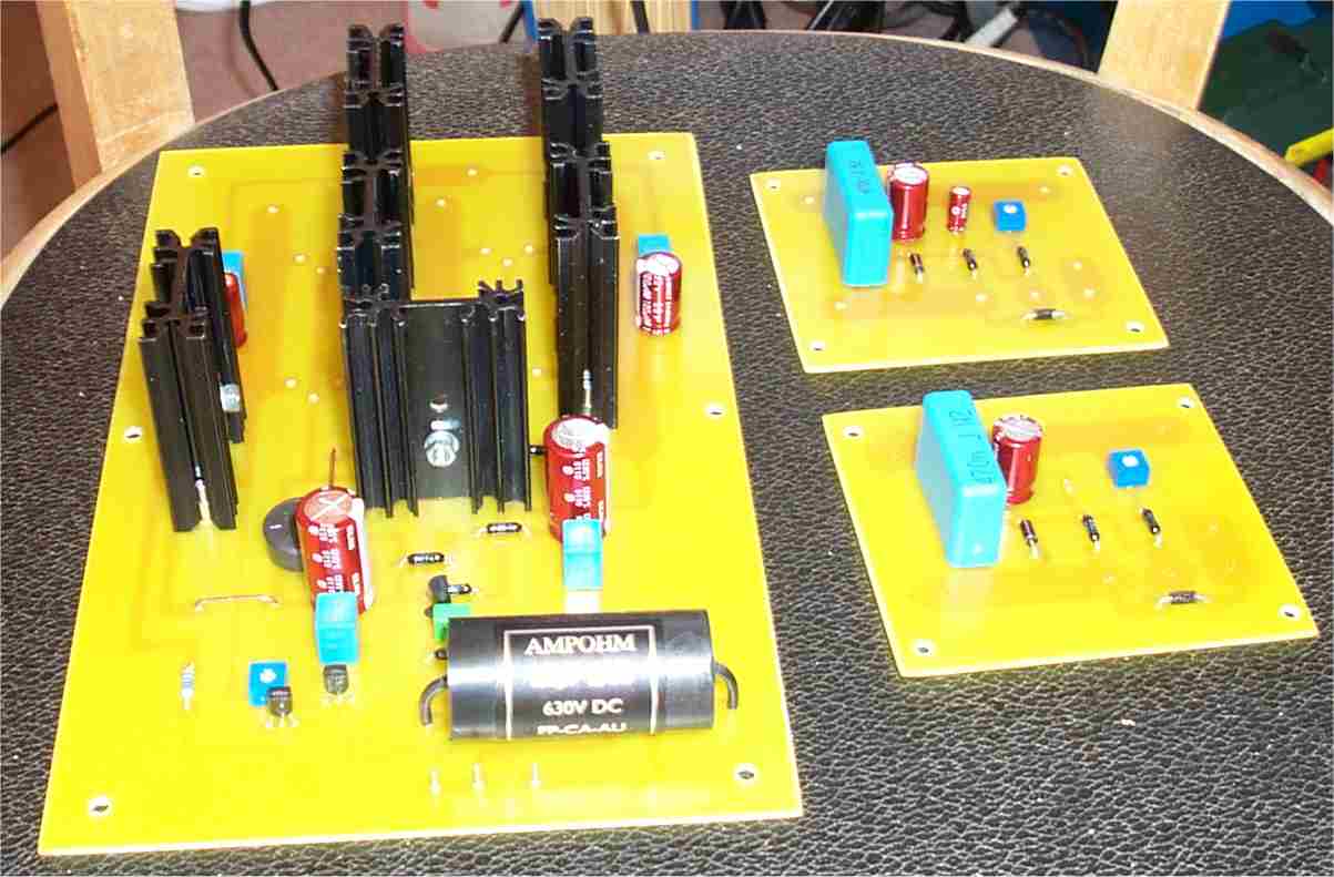
Photo. 1 The pcbs
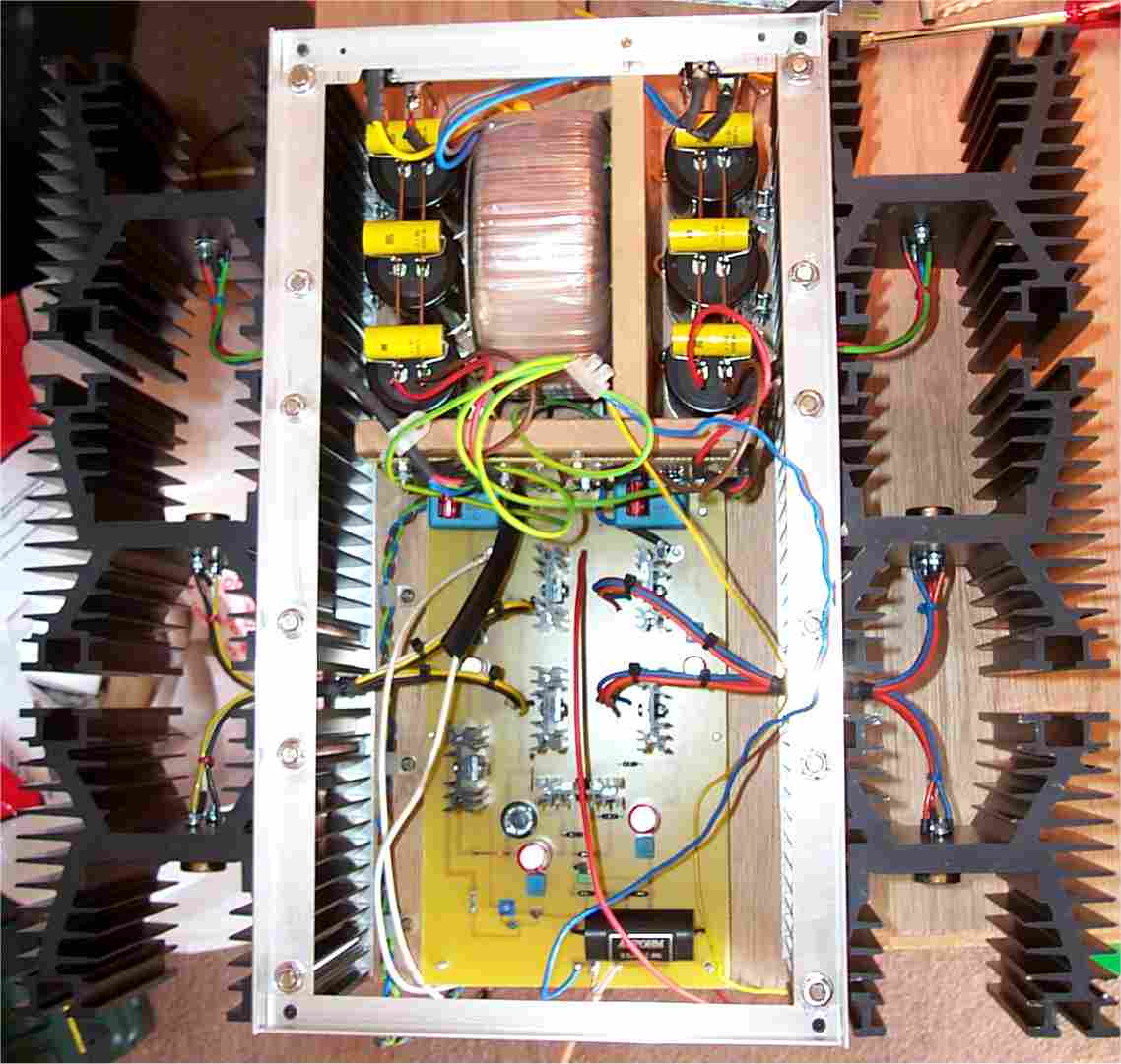
Photo. 2 Nearing completion, a plan view
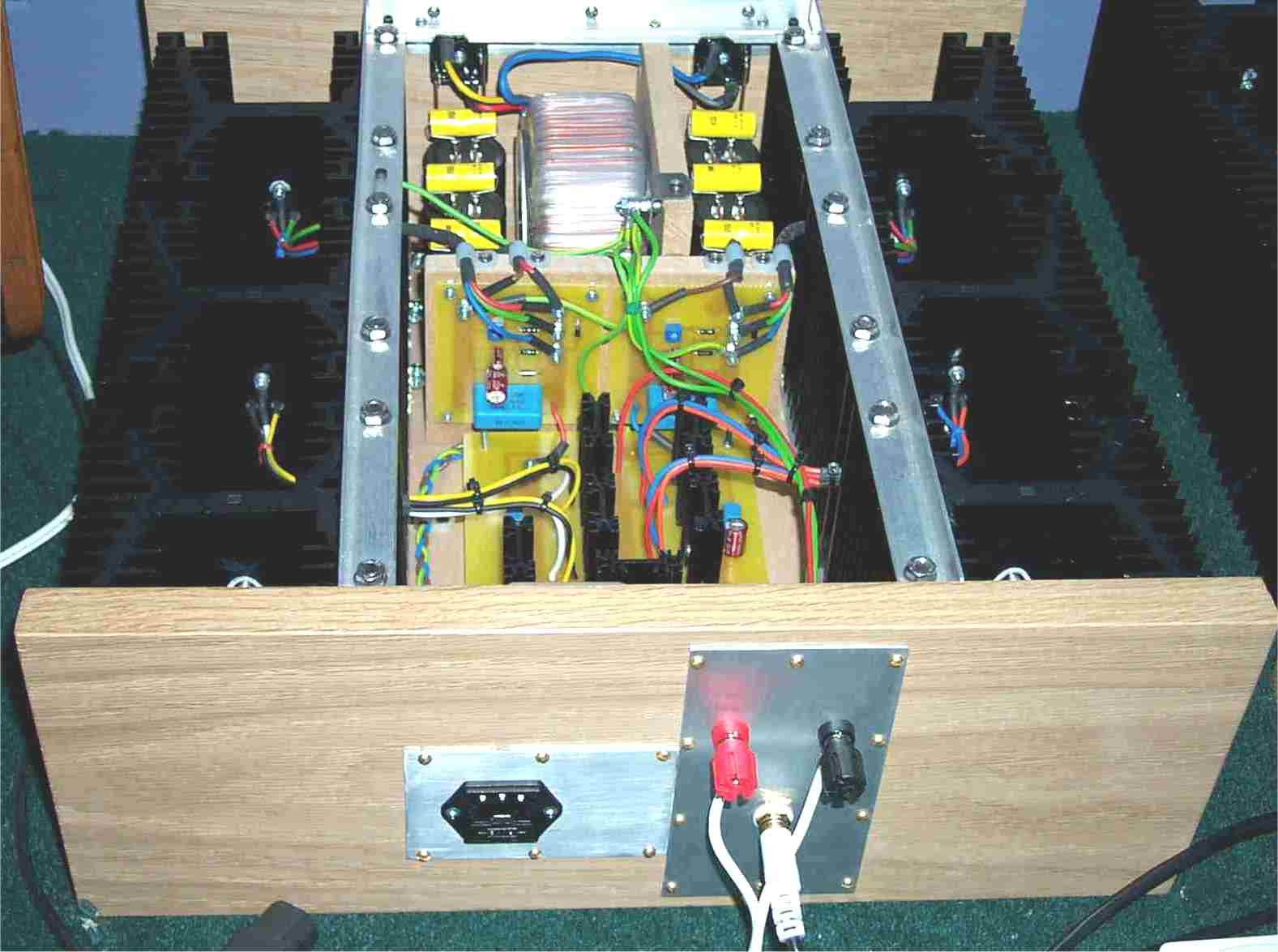
Photo. 3 The finished amplifier with top cover removed
HISTORY:Page created 04/11/2001
18/11/2001 Credits, pcb details and photos added
19/11/2001 pcb details corrected
21/11/2001 pcb overlays added
31/01/2002 R5/RV2 power rating notes added
04/02/2002 R5/RV2 notes revised and separated as an Addendum. RV2 value changed to 500R in Fig. 1 (was 2k)